![]()
Beautiful Plants For Your Interior
![]()
Beautiful Plants For Your Interior
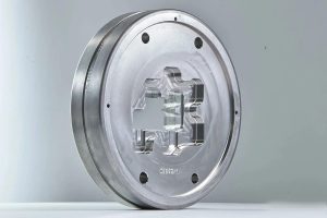

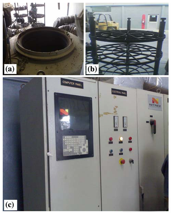
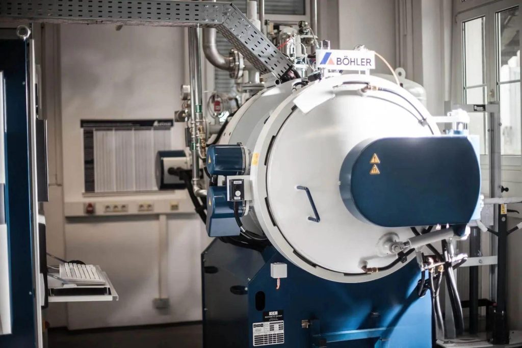
Nitriding of complex-shaped extrusion dies may lead to uneven nitriding layers, with certain areas in the working band region possibly failing to achieve the required hardness. The sample dies were gas nitrided under controlled nitriding potential. A two-stage gas nitriding process was adopted, combined with a local extrusion device to control the nitriding potential. The nitriding equipment, developed by NITREX Metal Inc. and commercially known as Nitreg, was used. The nitriding furnace, as shown in Figure 1, is of a top-loading design with a swingable cover, which can be selected to meet the process requirements and is capable of handling a wide range of applications and workpiece sizes. This nitriding system can maintain the preset nitriding potential value (Kn 1/4 pNH3 = pH2 ð Þ3/2, where p is the partial pressure of the constituent gas). Through continuous self-correction, the nitriding potential (Kn) value is kept within a certain range according to the needs of each processing stage. The system sets the flow rates of nitrogen and ammonia gas according to the preset program.
First, preheat the furnace and equilibrate it to the preset temperature (450°C) for approximately 3 hours. The air in the distillation chamber is replaced by a mixture of ammonia and nitrogen. The filling time (1 hour and 40 minutes) is calculated by the control system based on the furnace volume and Figure 3, and is automatically determined in each process stage. The control of temperature and gas flow is carried out to reach the set point Kn value, which depends on the ammonia dissociation percentage. The changes in Kn during the nitriding cycle are shown in Figure 2(b) and are recorded at intervals of 10 minutes. This Kn variation describes the reduction of the ammonia percentage from the first stage to the second stage (i.e., the increase in the atmosphere from the first stage to the second stage of ammonia dissociation). Before the next process stage begins, the heating stage will be automatically activated. Before the first and second stages, the heating time 1 and heating time 2 are set to 1 hour respectively. The processing time for the first and second stages is 1.5 hours and 3.3 hours respectively. The total nitriding cycle takes approximately 15 hours; however, the actual nitriding time is about 6.8 hours, corresponding to the heating 1 to the second stage, as shown in Figure 2(a). It should be noted that by adjusting the distillation chamber (i.e., Kn), the desired phase composition and desired thickness of the composite layer can be formed. The thickness and phase structure of the composite layer have certain effects on the performance of the mold. For extrusion molds, a deep shell is not necessary; a shallow shell with a maximum value of 250 lm is sufficient to form the composite layer within the 10% range of the total shell depth. As a deeper shell is formed, the surface may start to lose flexibility, which may lead to surface cracking, resulting in early maintenance of the mold and thus causing the press to stop.
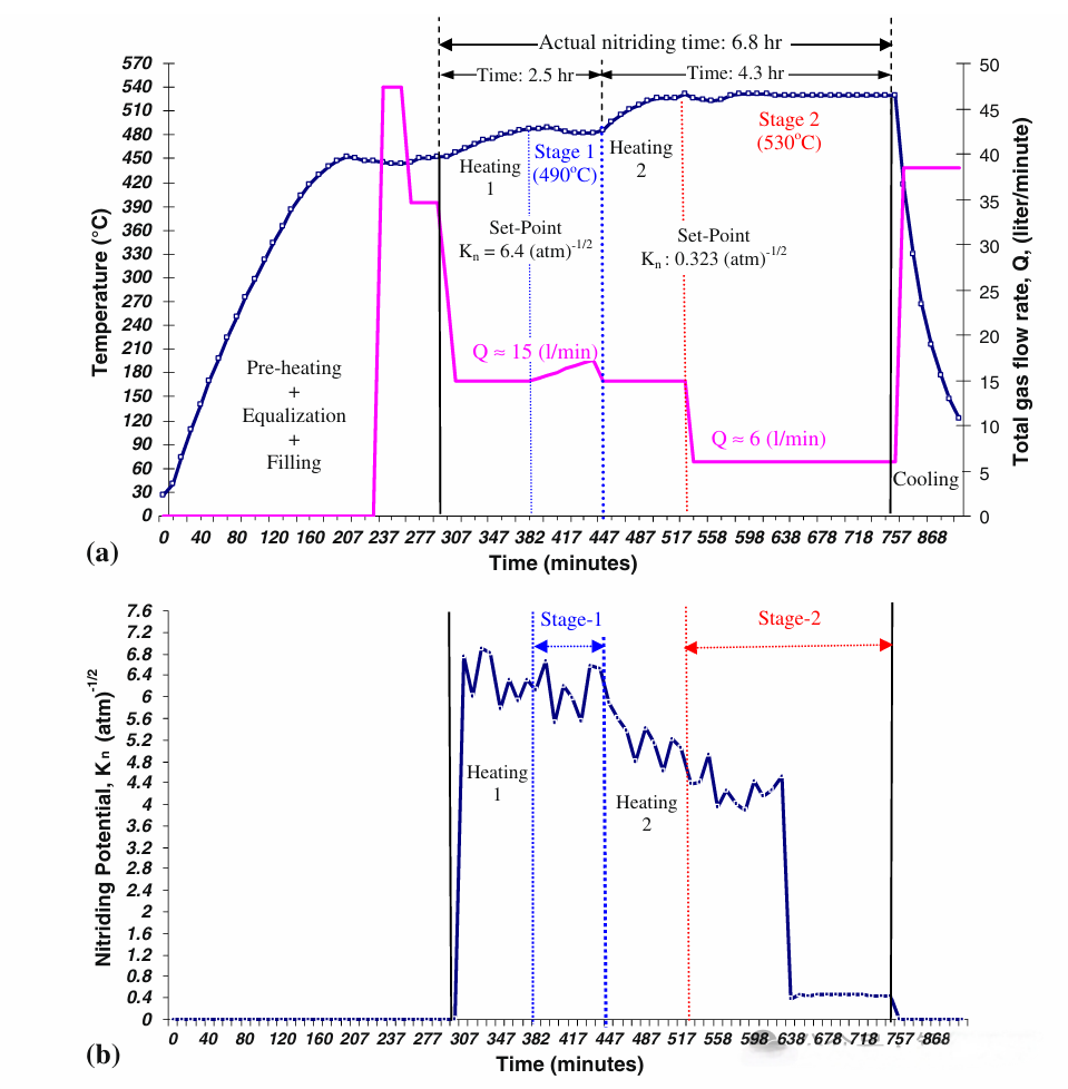
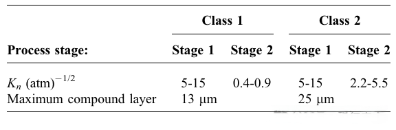
The changes in temperature (a) and nitrogenation potential Kn (b) during the two-stage nitriding process of AISI H13 specimens with different geometric profiles are shown in Table 1. This table presents the recommended range of nitrogenation potential and composite layer thickness for two-stage controlled gas nitriding of H11/H13 steel as recommended by AMS.
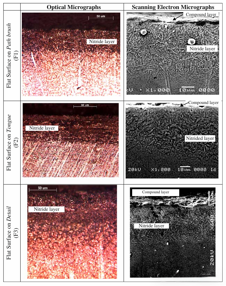
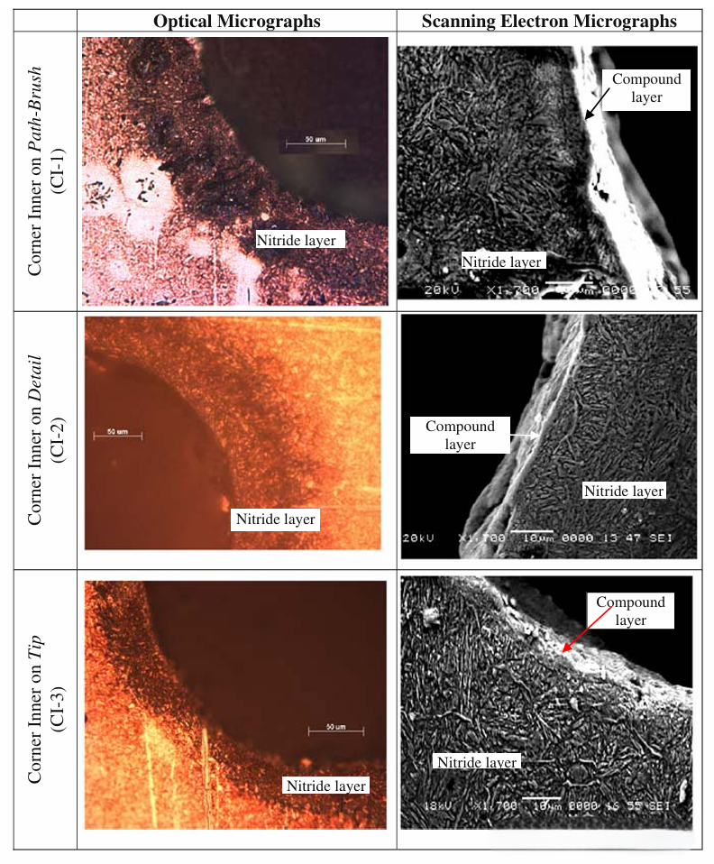
Results and Discussion: The microstructure was studied using optical and scanning electron microscopes, followed by microhardness measurements to observe the formation of the nitride layer and its uniformity across 15 different features included in the most common mold profile. The optical and scanning electron microstructures of the nitride cross-sections for all 15 features, as well as the corresponding hardness depth distributions, are shown in Figures 5 to 14. It can be observed that all microstructures are composed of the nitride layer on the outer surface. The nitride layer consists of diffusion zones with fine nitride precipitates (dark areas in the optical and thin section structures in the SEM micrographs), with or without a composite layer on the surface. It can be observed that the composite zones are more obvious in the SEM micrographs than in the Journal of Materials Engineering and Performance.
Although gas nitriding of the molds and other steel components is a mature surface hardening treatment, several aspects of the nitride layer still require attention and research. One important issue is that the H13 tool steel extrusion molds used for producing aluminum profiles have very complex shapes. To improve the uniformity of nitriding, it is crucial to identify the key geometric features in the molds that are related to the formation of the nitride layer. Then, corrective measures can be incorporated into the controlled nitriding process accordingly.
Different extrusion die profiles were collected from local extrusion factories, and some of the most commonly used profiles were modeled using Solid-Works software. The profiles were combined with local extrusion die manufacturing equipment and were cut into H13 blanks using CNC wire-cut EDM. All samples were nitrogenized using a two-stage controlled gas nitriding process.
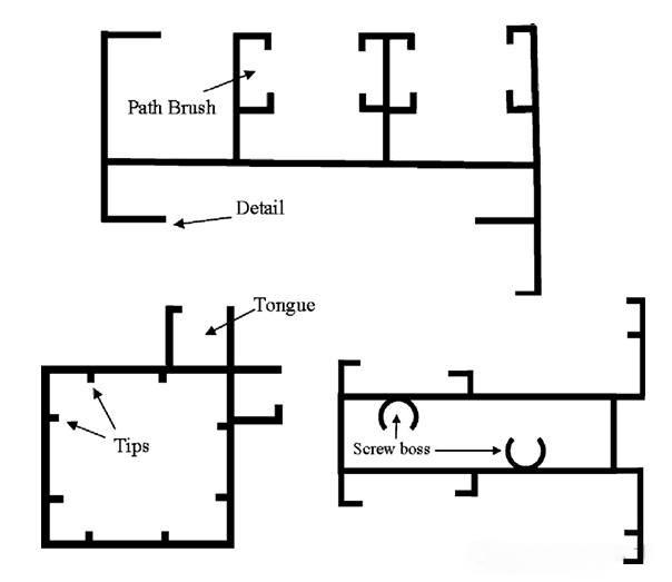
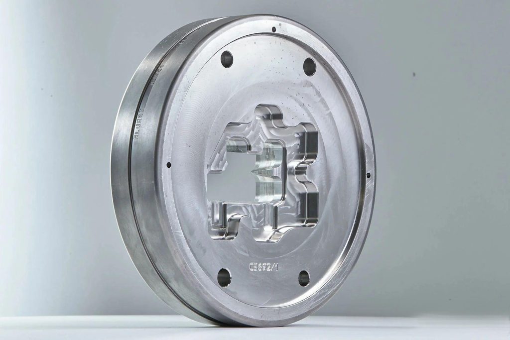
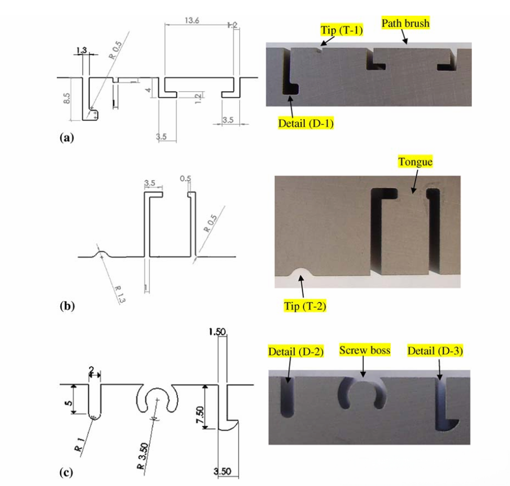
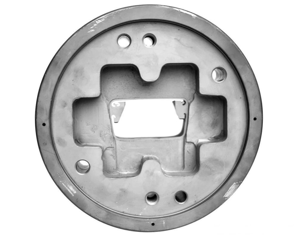
These three types of extruded profiles are representative. They are selected from approximately 150 mold profile drawings collected from the local extrusion industry. These five features, namely the screw boss, path brush, tongue, details and tip, are the most common and are typically found in almost every complex mold. Three samples were prepared by combining the most common and frequently used configuration files, as shown in Figure 2. The size diagrams and actual samples are presented. There are three different details (D-1, D-2 and D-3) and two tip types (T-1 and T-2). CNC wire cutting was used to produce the samples. The thickness of the samples was maintained at 5 mm. The sample material was H13 tool steel. The samples were heat-treated in an appropriate environmental control using a vacuum furnace to prevent decarburization. The heat treatment cycle included stress relief at 650°C, preheating at 815°C, austenitization at 1030°C, quenching, and final double tempering (first at 550°C, second at 650°C).
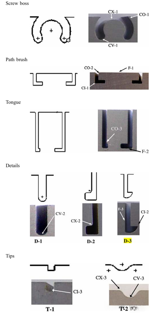
Preparation and microscopic examination of the nitride layer samples: Five mold profiles commonly used in the extrusion industry were carefully selected, and these were also identified in the actual mold profile diagrams.
(a) Screw boss: To be used later for securing the extruded part to the structure
(b) Path brush: Make grooves, and later install rubber liners on them.
(c) Tongue: A partially open rectangular extension part, usually connected to a hollow profile.
(d) Details: The small attachments of the main profile are actually secondary sub-features.
(e) Note: A very small protrusion, either sharp or round. These outlines contain some of the very common features found in the study.
These functions are classified into the following five categories: (a) convex surface (CX), (b) concave surface (CV), (c) inside the corner (CI), (d) outside the corner (CO), (e) plane (F).
The Lehrer balance diagram illustrates the relationship between the nitriding potential (Kn), nitriding temperature and the a, c¢ and e phases at equilibrium. This diagram can be used to observe the influence of the nitriding potential on the formation of the e or c¢ phase in the surface area. Assuming that the displacement in the Lehrer diagram caused by alloy elements is not significant, it can be applied to H13 steel. The critical nitriding potential value above which nitride iron is generated in the compound layer c0 Fe4Nande Fe3N ð Þ can be determined, as well as the nitrogen activity. The actual change in Kn also indicates that the compound layer will form on the surface. It can be clearly seen from the Lehrer balance diagram that when the Kn in the atmosphere exceeds the upper limit of the nitrogen concentration in the a zone (diffusion zone) at the nitriding temperature, the c0 Fe4N phase of the compound layer begins to form. Further increase in Kn leads to the formation of the e phase on the steel surface. Different category recommended range Kn values and the maximum allowable thickness of the compound layer were used according to the AMS per requirements classification. In addition, the thickness of the compound layer achieved in all 15 features is less than the maximum value specified by AMS. The hardness measurement was carried out at a specific position (depth) approximately 10 lm away from the surface. Each indentation point in the hardness-depth profile was the average result of five measurements at each position. It can be seen that the hardness-depth profile patterns of all features are the same, being the maximum near the surface and decaying towards the material core. However, although the samples were made of the same material and were nitrided under the same conditions, the hardness curves along the depth would be different. The core hardness measurements at these positions were 660 HV. The nitriding depth at each feature position was determined based on the hardness-depth profile, with the standard being the depth below the surface, and the microhardness being 10% higher than that of the core. The influence of the surface texture on the nitriding process will be described in the subsequent section.
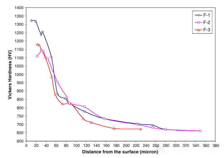
The selected inspection positions resulted in almost uniform and similar nitride layers. Additionally, a layer of 4 lm in thickness was achieved according to the requirements of the extrusion mold. From the case depth developed for feature F-3 (corresponding to the sectional detail D 3), it can be observed that the surface position and direction play an important role in controlling the case formation. Compared to the other two planes, the nitride depth of F-3 is relatively small, which can be attributed to the relatively indirect acquisition of nitrogen during the diffusion process. By comparing the hardness curves of the planes, the maximum hardness of F-1 is the highest, approximately 1300 HV, and decreases monotonically towards the core material. However, the maximum hardness of the other planes is within the range of 1150 HV. The results indicate that F-1 corresponds to the path brush, is more directly exposed to nitrogen, and the nitride layer is satisfactory. The same reason applies to the uniform and slightly thick composite layer of F-1.
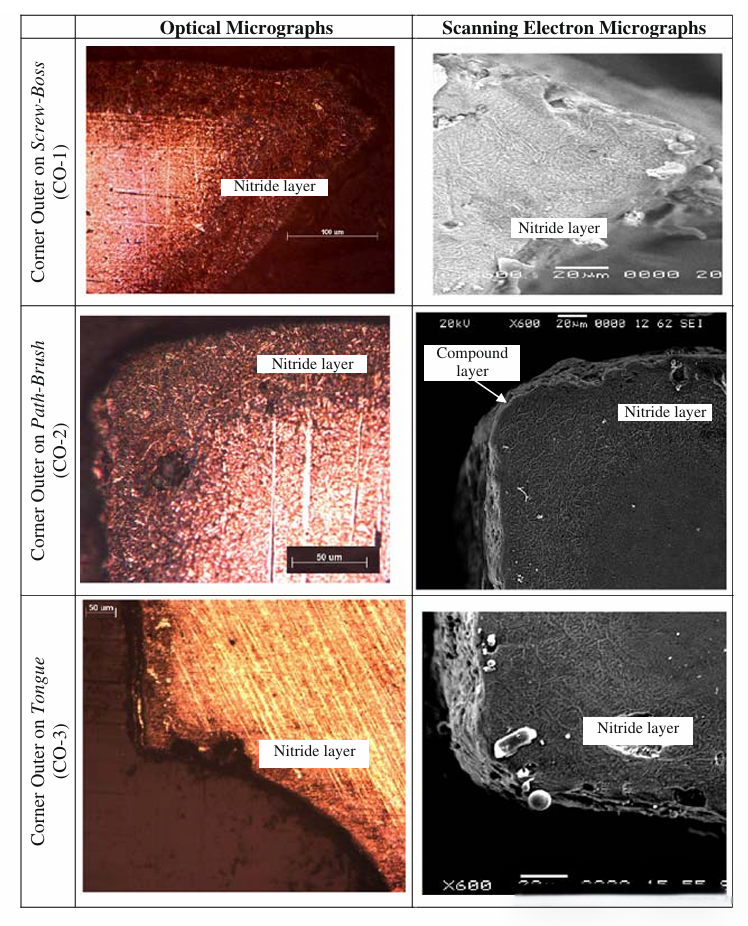
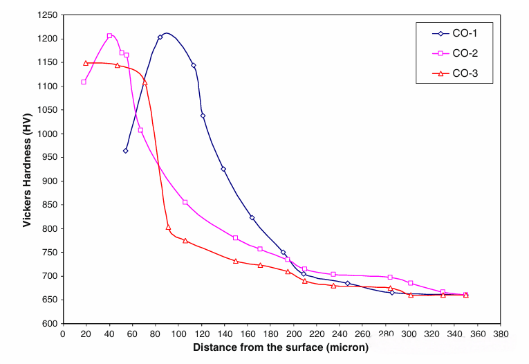
Despite the use of a controlled nitriding process, the extreme corner areas’ nitrogen over-saturation resulted in the “corner effect”. Due to the reduced toughness, the corner effect led to a significant decrease in the initial hardness value. For example, in the case of CO-1 (corresponding to the screw boss), this effect was significant, and it could be seen from the reduced near-surface hardness that very brittle and flaking nitride layers were obtained at the corner. Many problems encountered by aluminum extrusion dies occur when the fragments of this brittle and flaking nitride layer remain in the die bearing area when at the corner. In the cases of the right-angle outer corner features CO-2 and CO-3, this effect was observed to be smaller. Besides the features themselves, another factor that affects the efficiency of the nitriding process and the subsequent uniformity of the nitride layer is the position of the feature relative to the gap and depth. For example, feature CO-3 is located about 15 millimeters below the exposed surface, and the gap through which nitrogen enters is only 1 millimeter. Narrow and deep gaps have a significant impact on the nitride layer, and compared with the other two outer corner features CO-1 and CO-2, the depth of the nitride shell is reduced to 160 lm; in this case, the depth of the nitride shell is 200 lm. Moreover, the hardness curve of CO-3 is very steep, indicating a decrease in the bearing capacity of the nitride shell.
The thickness of the composite layer is comparable to the layer thickness corresponding to the planar feature, except for CX-2. The relatively uneven depth of the nitride shell and the absence of a compound layer at CX-2 may be related to the narrow position of the feature, resulting in an inability to obtain the appropriate nitrogen content during the diffusion process. At certain positions of the feature, the case depth may even be less than the estimated value (90 lm). This observation result also confirms the influence of the feature position and orientation on the nitridation kinetics.
The depth of the concave feature is relatively shallower than that of the flat surface. The thickness of the composite layer is approximately 3 lm, and it can be observed to be very uniform from the SEM micrograph. The hardness-depth curves at all concave positions are almost the same, with the maximum hardness ranging from 1150 HV, which is comparable to that at the flat positions.
The shape characteristics of the mold holes in the compression mold have a significant impact on the uniformity, depth and quality of the nitrided layer, as well as the surface hardness and hardness distribution. It is necessary to consider the influence of the mold contour on the nitrided layer in order to achieve the best mold design and extend the service life: